The Guitar Hero 3 Bot [Obsolete!]
Introduction : What you need : Hardware : USB Interface : Software : Videos : Guitar Hero 2 : DLC! : Whammy : SP Paths : Kits
USB Interface
Part 3 - Connecting the USB interface
The connectors on the board
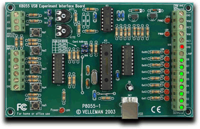
The image below shows the GND (Ground) for the digital outputs (red) and the 8 digital outputs (green):
When a digital output is activated a connection is made between ground and the output in question.
Therfore the (-) connector of your power supply needs to be connected to ground, the (+) connector of your power supply needs to be connected to the common wire of the relay board, and the other 7 relay wires need to connect to outputs 1-7 of the USB board.
If you plan to use my software (provided later on) this is the order in which it assumes they are connected:
1: Green
2: Red
3: Yellow
4: Blue
5: Orange
6: Star
7: Strum
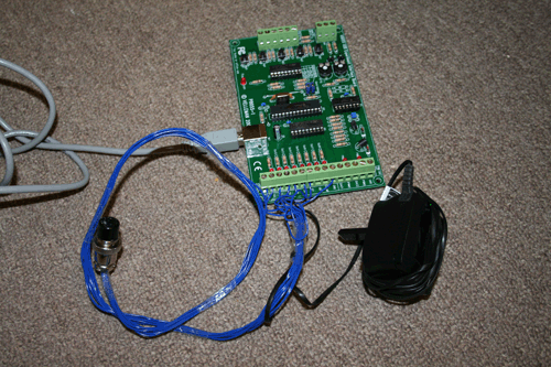
Hopefully it looks like this

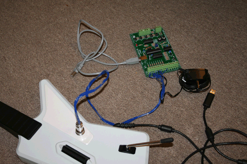
And finally, with the guitar

Introduction : What you need : Hardware : USB Interface : Software : Videos : Guitar Hero 2 : DLC! : Whammy : SP Paths : Kits
Copyright © Paul Ridgway 2009 | Pictures by Amanda Taylor | HTML Layout & Base code by James Ridgway